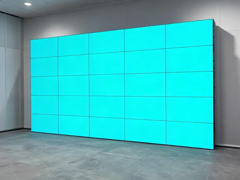
Fine-pitch indoor canvas
For close viewing and dense information, with pitch, moiré risk, module flatness and low-brightness calibration reviewed together.
Open the catalog →
Start with ambient light, minimum viewing distance, content type and service access. The result is a display architecture that an AV consultant can inspect, test and maintain.
These planning bands are evaluation starting points, not product guarantees. Final values must be verified against the selected Barco series data sheet, cabinet layout and site acceptance plan.
| Optical design inputs | |
|---|---|
| Pixel pitch study | Model from minimum viewing distance and critical text size; compare approximately 0.9–2.5 mm for close-view indoor concepts before selecting a series. |
| Brightness target | Measure room illuminance at the display plane. Control-room and lobby targets differ; dimming range and black-level behavior matter as much as peak nits. |
| Color workflow | Define source gamut, white point, calibration interval and camera interaction before factory acceptance testing. |
| Mechanical and service inputs | |
| Wall geometry | Document active width, active height, cabinet matrix, permissible flatness, floor loading and mounting datum. |
| Maintenance path | Front service reduces rear clearance but can change module extraction procedure; rear service simplifies some interventions but needs a safe access envelope. |
| Resilience | Record power-feed topology, signal redundancy, spare-module policy and recovery test steps in the commissioning file. |
Each path changes the balance among viewing distance, room integration, service access and operating continuity.

For close viewing and dense information, with pitch, moiré risk, module flatness and low-brightness calibration reviewed together.
Open the catalog →
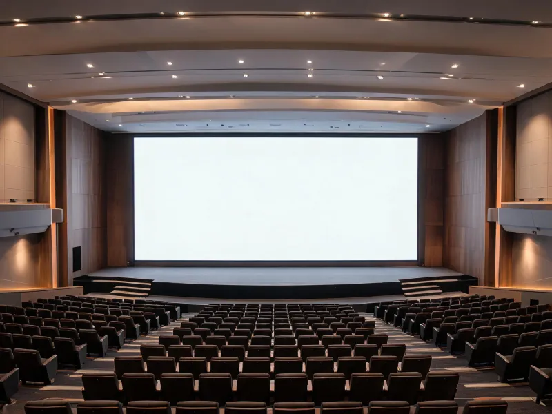
For corporate and public spaces where viewing zones, content scale, structural interfaces and controlled brightness set the design.
Compare deployment inputs →
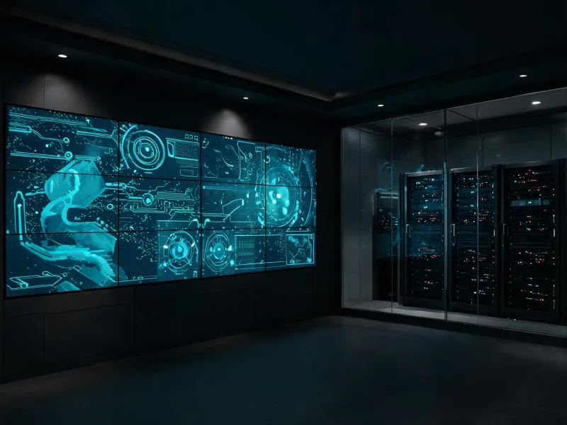
For continuous-use rooms where redundant signal paths, event logs, spare strategy and documented recovery steps shape acceptance.
Plan lifecycle support →These are representative project briefs rather than named-customer claims. Each records the context, engineering route and acceptance evidence expected for its application.
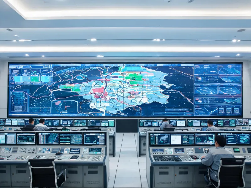
Background: persistent dashboards. Process: map signal and power failure modes. Result: an acceptance script that times source recovery and module replacement.
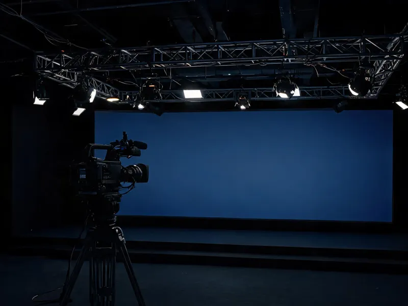
Background: multiple cameras and shutter settings. Process: run moiré, refresh and color tests. Result: a documented operating window for camera, processor and wall.
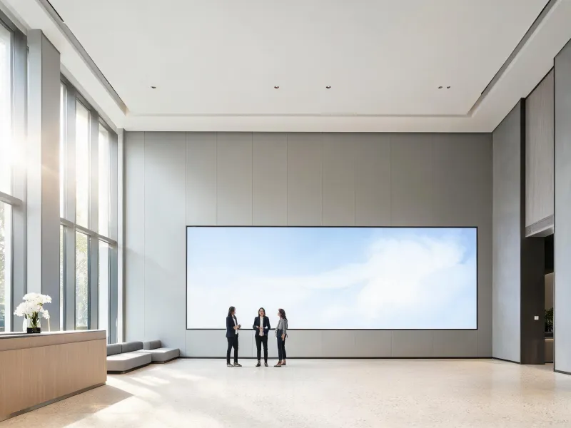
Background: changing daylight and close traffic. Process: measure illuminance and sightlines. Result: brightness scenes, content-safe zones and a planned cleaning route.
Share viewing distance, wall dimensions, ambient-light readings, source formats and expected duty cycle. The initial response can then identify assumptions and missing tests instead of guessing a model.